Shanghai Tower
Envelope System
In designing the façade for the Shanghai Tower, Gensler introduced a combination exterior and interior curtain wall system totaling 210,000 square meters (2.26 million sf) of glazing area.


Fig 1. The Shanghai Tower: a vertical spiral rotating tower ( Source: ZELJIC, 2010)
Building Geometry
The tower’s profound twist expression is the result of its geometry, which can be broken down into three key components that are controlled in total by four variables.
Horizontal profile: The profile shape is based on an equilateral triangle. Two tangential curves offset at 60 Degree were used to create a smooth shape. This shape is driven by two variables: the radius of the large circle and its location relationship with the center of the equilateral triangle (profile). It should be noted that the actual shape of the profile is independent from the remaining two key geometric drivers. As a result, Gensler had the ability to look at the effect of modifying the horizontal profile and the impact such changes had on the tower form at all stages of the design.
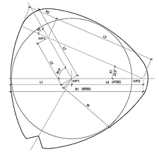
Fig 2. Horizontal profile geometry (Ge, 2012)
Vertical profile: The concept of the form is to take the horizontal profile, extrude it vertically, and conform to the vertical profile. From a functional point of view, it was important to maintain a wide footprint for the lower third of the tower, with a slender footprint at the upper third—a reduction of about 55% overall. This proportional distribution allowed for large lease spans within the office portion of the tower and smaller spans within the upper-level hotel/boutique offices. Early in the design, it was found that a basic exponential curve provided the desired result. This is the same basic formula used in the finance industry for continuous compounding and/or discounting. Adjusting the two values in the horizontal profile and this third value in the vertical profile, complete control of vertical ratio, gross floor area and building form have been done.

Fig 3. Vertical profile geometry ( Source: ZELJIC, 2010)
Rate of twist: This is a simple linear rotation from base to top. The fact that this final value can be changed independently to allow great flexibility in the design stage, especially in selecting the best combined overall building performance.
Wind Tunnel Testing Results
The wind climate model was based on local surface wind measurements taken at Hong Qiao International Airport and a computer simulation of typhoons provided by Applied Research Associates, Raleigh, North Carolina. All testing was conducted on a 1:500 model.
The Gensler design team had anticipated that significant reduction in both tower structural wind loading and wind cladding pressures could be established if the building further improved its proposed geometry following the variables previously explained. To establish the best possible case for reducing these loads, several scenarios were proposed involving rotation at 90°, 120°, 150°, 180° and 210°, then scaling off 25%, 40%, 55%, 70% and 85%. All these scenarios were analyzed against each other and then compared to the base case scenario that was proposed, in the form of a tapered box.
Results acquired through this process have shown that a scaling factor of about 55% and rotation at 120° can account for up to 24% savings in structural wind loading and cladding pressure reduction as compared to base-case tapered box. This equates to about $50 million (USD) in savings in the building structure alone.
Additionally, it helped to optimize and distribute maximum cladding loads on the building while maintaining desired aesthetics. Aesthetic concerns prevented the 180° rotation from being pursued, even though it would reduce loading by an additional 9%.
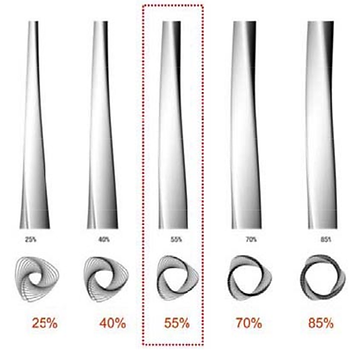

Fig 4. Wind tunnel study scaling models ( Source: ZELJIC, 2010)
Fig 5. Wind tunnel study rotation models ( Source: ZELJIC, 2010)
Curtain Wall Support System
How to realize the reverse rising curtain wall facade is a key to the whole tower design. The special characteristics of the curtain wall are that the geometric modeling is very complex, at the same time, the visual effect is highly demanding. In the curtain wall supporting system selection stage, structures have been proposed to support three rigid grid schemes, which has the advantages of small deformation of the structure and less difficulty. However, the scheme is of great influence on building façade.
Based on the requirement of light building curtain wall, eventually the flexible hanging support structure system was adopted. Curtain wall supporting structure system composes three independent parts according to different zones: Zone One, Zone Two to Zone Eight and the top part of the tower crown. Using partition layout can effectively reduce the interaction between the curtain wall supporting structure and main structure, thereby reducing the internal force of structural members, optimizing the member section and form.
The district curtain wall supporting systems are three independent basic units, which adopt the same structure system. Specifically, it is the " steel structure + radial struts + horizontal bracing". According to the torsion form of the construction plan, the supporting structure is radial supports that correspondingly narrow the size upward gradually and rotate 1 Degree to each layer. And they connect the device layer by ring beams and suspender at different districts.
The horizontal radial pipe strut supports consist of a 219 mm diameter pipe (with varied but mainly 22 mm wall thickness) that transfers the exterior façade lateral load to the inner circular building slab edge. The radial strut pipes are rigidly connected with the horizontal girt, while using a hinge connection on the other side at the interior slab edge steel support to allow the exterior façade to move up and down relativing to the inner structure.
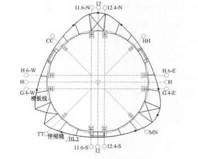

Fig 6. Plan layout of curtain wall support structures of typical zone
Fig 7. Torsinal force apply to ring beam
( Source: Yin & Jiemin 2011)
To carry the gravity load of the façade and façade support structure, two 60-to-80 mm high-strength rods (depending on the zone) are hung from the mechanical room/refuge area above, with a robust steel structure designed within, to the horizontal 356 mm ring pipe beams at 4.5 m (4.3 m in Zone Seven and Zone Eight) on-center vertically at every strut location, including an amenity floor that uses steel bushings instead of perpendicular struts to limit lateral movement. Steel bushings move in vertical direction to allow for expected combined closing and opening movements to be largest at Zone Two, at 114 mm.

Fig 8. Tower curtain wall support system (CWSS) (Source: Yin & Jiemin 2011)
Final Glass Selection
The Gensler team has proposed the following generic glass types for two major curtain wall systems:
-
Curtain Wall A: 26 mm laminated glass assembly - 12 mm low-iron glass +1.52 mm SGP interlayer + low-e coating + 12 mm low-iron glass.
-
Curtain Wall B: 30 mm insulated glass assembly - 10 mm low-iron glass with low-e coating + 12 mm air space + 8 mm low-iron glass. The middle portion of the panel between “chair rail” to the finish floor will have dissolving frit pattern from 15% down to 75% and 15% again.

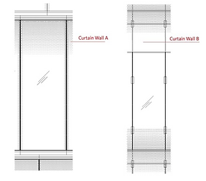
Fig 9. Curtain wall A and B
( Source: ZELJIC, 2010)
Final Curtain Wall A design will accommodate about 129,915 square meters (nearly 1.4 million sf) of glass, and about 28,315 curtain panel units in total. From 144 panels per floor, there will be eight different panel types, with a larger number of same panel types (95%) except on accent V-strike areas. The efficient design approach here also includes glass and aluminum fabrication tolerances. Each curtain wall unit will be hung from the perimeter girt. Control points for each unit are established through geometry analysis, as discussed earlier, and are set at 400 mm outward offset from the girt centerline.
The intention with setting this dimension was to address all profile conditions between two adjacent floors resulting from twist and taper. The largest “ledge” projections are about 600 mm, representing about 15% of total conditions, with about 350 mm being the more typical condition (70%) and extending under the glass line above approximately 80 mm. The total vertical aluminum mullion depth is 114 mm plus addition of the glass fin, continuously connected to back side of the mullion. The glass fin is a laminated assembly with a total 26 mm thickness and up to 300 mm in depth. The top of the building at Zone Nine has an iteration of vertical mullion without a glass fin due to easier maintenance and exposure to the weather conditions. The total depth of mullion at this zone is designed at 250 mm.
Another variation of the vertical mullion is at the area of accent “V” strike. Vertical mullions here are used to house and support a dense LED lighting fixture layoutl using a deeper mullion was a practical necessity.

Fig 10. Curtain Wall A: Panel types
Fig 11. Curtain Wall A system
Lastly, the exterior wall at mechanical floor intake and exhaust areas (each zone division) is a variation of the overall system that allows flexibility for building maintenance equipment use. Everywhere else, mullions were intended to be used with minimum depth and profile width, corresponding to the general design intent of maximum transparency. To address the issue of excessive torsion on the girt resulting from 400 mm offset of the curtain wall control point, Gensler’s team has proposed a rigid moment frame connection as part of the inset into each vertical mullion stack. Units will be delivered to the construction site prefabricated with this element and will be hanged as standard segmented unitized panels.
( Source: ZELJIC, 2010)
( Source: ZELJIC, 2010)
Gensler’s façade design team had a key goal in mind - designing a system that will achieve flexibility for procurement and encourage competition between the best fabricators in China and elsewhere in the world, allowing the client have more balanced and controlled cost. Designing a system as described allows that approach; in the coming months, it is expected that the final curtain wall contractor will be selected, which will follow with a series of performance and visual mockups and shop drawings documentation.
To address thermal comfort in the public zones of each atrium, a series of computational fluid dynamics studies were conducted for each of three atria per zone. Additionally, horizontal projections act as exterior fin shades and, with the frit pattern on glass exterior surfaces, helpinng to reduce glare.
Design constraints for Curtain Wall B are considerably different from those analyzed for Curtain Wall A, as this system is designed not to be pressure-equalized since it is in enclosed spaces and with maximum wind loading pressures of about 2.1 kPa, anticipated to be experienced during the construction sequence with partial exposure of the system to outside pressures. Additional constraints of stack effect and airflow through open atria are controlled by very tight air infiltration criteria—1.0 liter/m2/sec at 75Pa. As stated, extensive computational fluid dynamics studies were conducted to confirm both thermal comfort and air velocity.
The most critical issue for Curtain Wall B was a requirement for one-hour fire-rating of all atrium glazing and CWSS assemblies, where Curtain Wall B is a major component. Several options were proposed, and more testing were conducted. Fig 12 and 13 represent the current design for Curtain Wall B. It should be noted that a “stick system” approach has been suggested to address the fire protection concept more thoroughly.
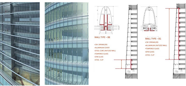
Fig 12. Curtain Wall B system
Fig 13. Current design for Curtain Wall B system—atrium view
( Source: ZELJIC, 2010)
( Source: ZELJIC, 2010)
Light Pollution Studies
The light pollution category was the most impactful variable in the overall exterior wall concept design and glass selection. In China’s urban districts, light pollution is considered as a harmful impact of glass reflectance out to surrounding residential, civic or public buildings or institutions. The ratio of glass on the building cannot be more than 70%, and the glass has to have reflectance that does not exceed 15%.
The Shanghai Tower’s Exterior Curtain Wall A glass ratio is very high, at about 87% (including spandrel area), and the Interior Curtain Wall B has a glass ratio of about 60%. With these high glazing ratios, the Gensler team needed to prepare a light pollution study conducted by a third-party consulting group. Two final schemes—“staggered” and “smooth” were selected for testing in a three-kilometer radius of the surrounding neighborhood.
Considering all of the variables involved, the ultimate result was purely geometric, as the curtain panels confirmed the modeling and testing of both scenarios with the Ecotect model. Simply put, glass perpendicular to the ground reflects less than glass angled to the sun. The largest angle on the tower was about 9°. The glass selected for the exterior will have minimal visible light reflectance of about 12%. However, Ecotect results revealed a difference favoring the staggered system, which ultimately became the system recommended by Gensler’s façade design team.
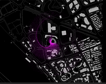
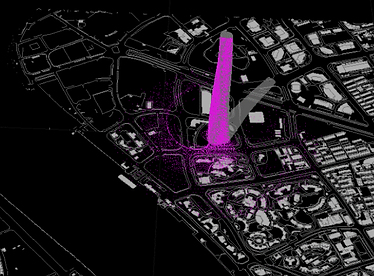
Fig 14. Light pollution analysis (Ge, 2012)